BADAL X Surgical Technique
video surgery femur stage 1 and 2
BADAL X OFI-C SURGERY
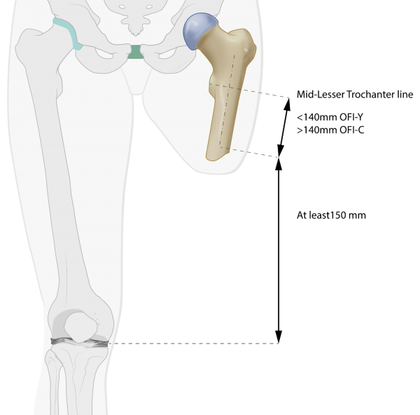
Fig C1: Pre-surgical planning
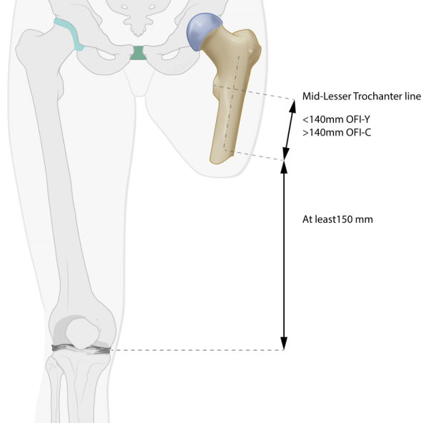
Calibrated AP X-rays and/or CAT scans and planning software (Traumacad) are used to: define the BADAL X implant type and size and to calculate the exact level of the bone cut. The knee joint space of the contra-lateral limb is used as reference to match the knee flexion axis of the external prosthesis exactly with the knee joint space of the sound limb. That means that in cases with long femur remnants the planned bone cut should be at least 150mm proximal of the ipsilateral medial knee joint line. The length of the BADAL X DCA is estimated based on the thickness of subcutaneous fat layer in the planned stoma area. In average DCA size 90 is used for application in transfemoral amputees. DCA size 100 and 110 for more obese persons.
BADAL X is implanted in a one-, or two-stage surgical procedure. In cases where there is few soft tissue coverage of the residual bone, BADAL X may be installed in a single surgical procedure.
Surgery is performed under general or spinal anesthesia including prophylactic intravenous antibiotics e.g. vancomycin (1 g) or cephazolin (2 g) at induction of anesthesia. Surgery is performed with correct supine positioning of the subject and draping and prepping following local standard orthopedic protocols.
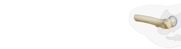
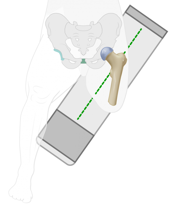
Fig C2: Surgery stage one for long femur

BADAL X implant OFI-C (curved) is used in cases with femur remnants longer than 140mm, measured from the mid-line of the lesser trochanter to the tip of the femur. In these cases the diaphyseal part of the femur makes a small curvature in the sagital plane which requires a curved implant.
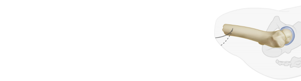
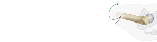
Fig C3, C4, C5: Skin incision

A mediolateral moon- or smiley-like skin incision is performed to create a slightly longer anterior flap. If necessary, redundant skin and soft tissue is excised with with the aim to create a tight and trimmed soft tissue coverage of the femur tip.
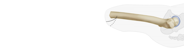
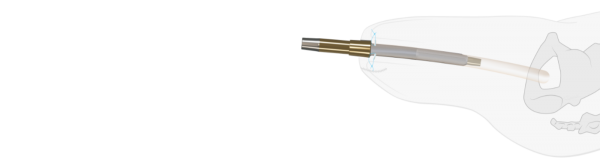
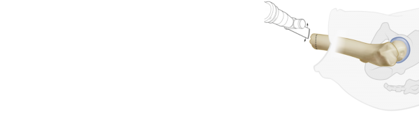
Fig C6: Cutting femur tip with oscillating saw
After releasing any tethering tissue, nerves are identified and, if present, any existing neuroma excised. The distal end of the femur is cut with an oscillating saw according to calculations in the pre-surgical plan.
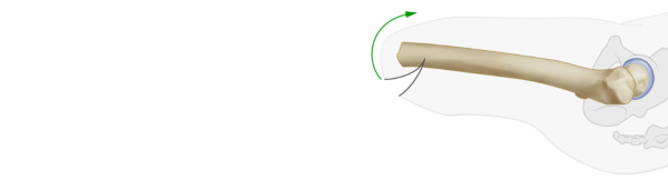
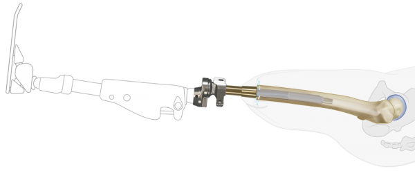
Fig C7, C8: Femur reaming with curved rasp and hammer
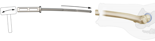
In cases with a narrow medullary canal, standard non-cutting flexible reamers under x-ray imaging may be used and finally, the intramedullary cavity is reamed by hammering in and out the Curved Rasps. Reaming is terminated at the rasp diameter equal to the diameter of OFI-C stem selected in the pre-surgical plan. Note that the diameter of the selected OFI-C stem is equivalent with the diameter of the last used Curved Rasp to obtain optimal press-fit fixation
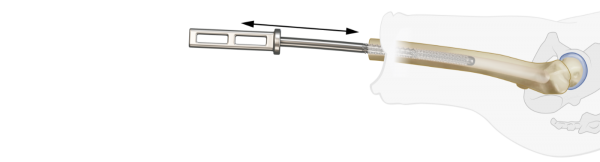
Fig C9: Femur tip preparation with Distal Tip Rasp
The Distal Tip Rasp is used to create a plane exactly perpendicular to the longitudinal axis of the femur.
Fig C10: Preparation of myodesis
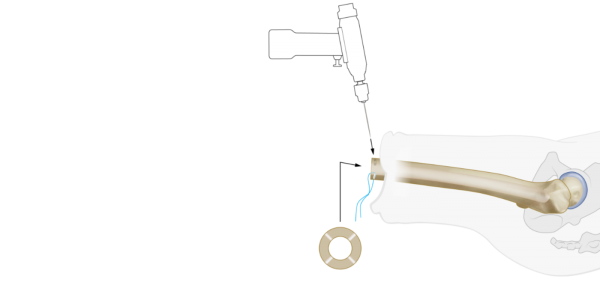 Four 1.25mm holes are drilled into the femur tip and preloaded with Vicryl CP-1, CT-1 absorbable sutures. These sutures are used for the myodesis later on.
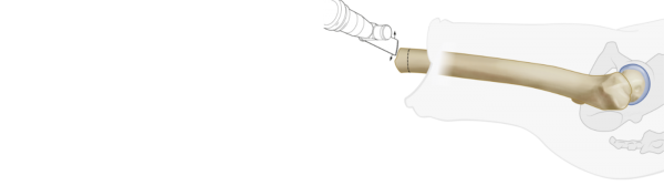
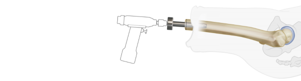
Fig C11, C12: Insertion of OFI-C
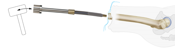
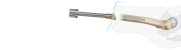
The OFI-C stem is placed on the Installer and press fit hammered into the femur.
Fig C13: Placement of Endcap
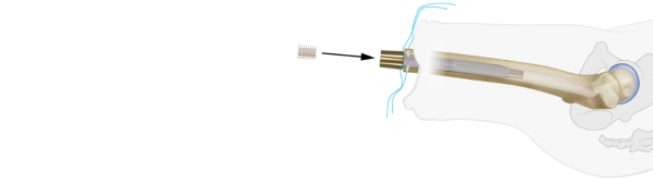
The OFI-C is delivered with an Endcap to prevent soft tissue ingrowth in the distal taper.
Fig C14: Completion of myodesis
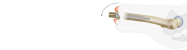
After thoroughly rinsing the wound, a myodesis is completed by suturing the fascia layers of the thigh musculature to the distal tip of the femur with the trans-osseal Vicryl CP-1, CT-1 absorbable sutures. Once this is completed, the location of the future stoma is determined and subcutaneous fat overlying the distal tip of the OFI-C stem is removed.
Fig C15: Skin closure
Wound closure is performed per standard technique with application of a stump pressure bandage. The surgical procedure is finished with intraoperative radiographic confirmation of the position of the OFI-C stem.
BADAL X OFI-C STEP 2
Surgery is performed under general or spinal anesthesia including prophylactic intravenous antibiotics e.g. vancomycin (1 g) or cephazolin (2 g) at induction of anesthesia. Surgery is performed in supine positioning of the subject and draping and prepping following local standard orthopedic protocols.
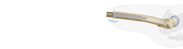
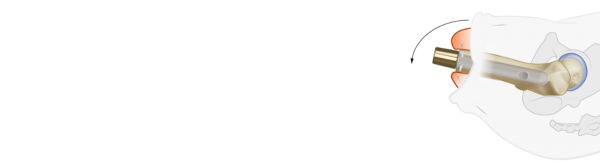
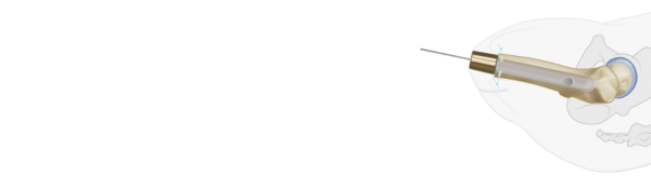
Fig C16: K-wire insertion
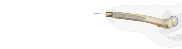
A guide-wire is used to identify the center of the BADAL X implant.
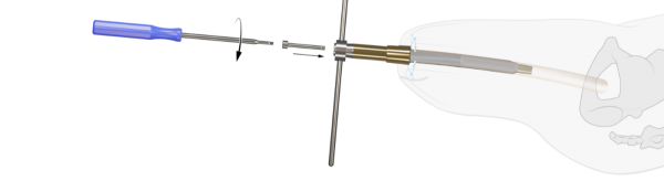
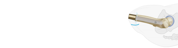
Fig C17: Skin incision
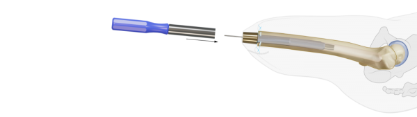
The Coring Device is passed over the guide-wire to cut the skin and create the stoma.
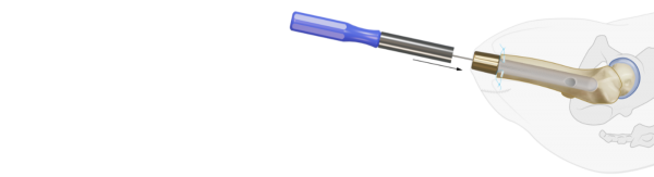
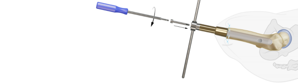
Fig C18, C19: DCA placement
The appropriate DCA is selected based on the thickness of the soft tissue layer in the stoma area. It is recommended that 2 to 3 cm of the gold coating of the DCA protrudes through the skin. The taper side with the two protruding pins of the DCA is inserted in the BADAL X implant and secured with the M6 Locking Screw using the Retainer and Hexa 4 Screwdriver. Use the Hammer and Punch to carefully further press the DCA male taper into the female taper receiver of the implant. Again use Retainer and Screwdriver to re-tighten the M6 Locking Screw. The stoma is covered with gauzes. Therby unfold a 10x10 cm gauze, wrap it around the DCA and tie it tightly around the DCA. This procedure may avoid minor bleedings from the stoma.
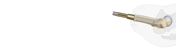
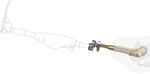
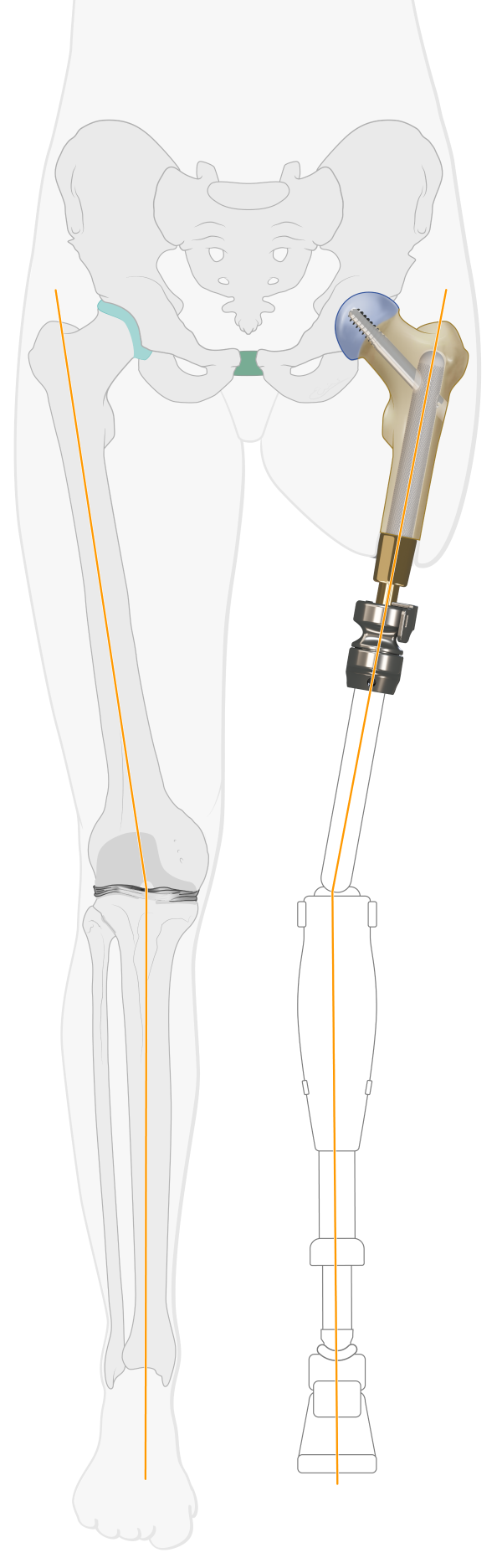
Fig C20: Connector placement and prosthetic alignment
One week after stage two surgery or 3 weeks in case of single stage surgery the male part of the Luci Connector is placed on top of the distal DCA taper and secured with the M14 Abutment Screw. Preferably a certified prosthetist is required to attach the prosthesis, adjust the length and align the prosthesis in the frontal and sagital planes. Components (knee/foot) from the existing socket prosthesis are used to attach to the BADAL X. No specific prosthetic components are required to be used in combination with BADAL X. Based on the amount of hipflexion contracture and the length of the remnant in transfemoral amputation levels, the appropriate Offset Plate is selected. The Offset Plate is supplied with the BADAL X Connectors and used to compensated for the hip flexion contractures. During the first years after BADAL surgery the flexion contracture of the hip often decreases which may allow a smaller offset. The rule of thumb is that a smaller offset is better, because walking with a smaller offset is more efficient (less energy consumption). In femoral BADAL X, apply 7 degrees valgus between the connector and the prosthesis to restore the physiological leg axis alignment.
Rehabilitation starts immediately after fitting of the prosthesis (see rehabilitation protocols)
BADAL X OFI-Y SURGERY
Fig Y1: Pre-surgical planning
Calibrated AP X-rays and/or CAT scans and planning software (Traumacad) are used to: define the BADAL X implant type and size and to calculate the exact level of the bone cut. The length of the BADAL X DCA is estimated based on the thickness of subcutaneous fat layer in the planned stoma area. In average DCA size 90 is used for application in transfemoral amputees. DCA size 100 and 110 for more obese persons.
BADAL X is implanted in a one-, or two-stage surgical procedure. In cases where there is few soft tissue coverage of the residual bone, BADAL X may be installed in a single surgical procedure.
Surgery is performed under general or spinal anesthesia including prophylactic intravenous antibiotics e.g. vancomycin (1 g) or cephazolin (2 g) at induction of anesthesia. Surgery is performed in supine positioning of the subject and draping and prepping following local standard orthopedic protocols.Unfortunately, this subpage is under construction
Fig Y2: Surgery stage one for short femur
BADAL X implant OFI-Y is used for femurs shorter than 140 mm between distal femur tip and mid-line of the lesser trochanter. For optimal primary stability, OFI -Y has an additional fixation of a gamma-type Lag Screw through the prosthesis into the femoral head.
Fig 11a: Patient positioning
The patient is supine positioned on the traction surgery table with the contralateral leg suspended in the leg rest to allow appropriate X-ray imaging of the hipneck in AP and sagital plane.
Fig Y3, Y4, Y5: Skin incision

A mediolateral moon- or smiley-like skin incision is performed to create a slightly longer anterior flap. If necessary, redundant skin and soft tissue is excised with with the aim to create a tight and trimmed soft tissue coverage of the femur tip.
Fig Y6: Cutting femur tip with oscillating saw
After releasing any tethering tissue, nerves are identified and, if present, any existing neuroma excised. The distal end of the femur is cut with an oscillating saw according to the calculations in the pre-surgical plan.
Fig Y7: Femur reaming with Rigid Reamers
The medullary canal is carefully reamed by hand with Rigid Reamers(drills) under constant alternating AP and sagital Xray imaging guidance to check the correct central position of the Rigid Reamer. Reaming is terminated at the Rigid Reamer diameter equal to the diameter of OFI-Y stem selected in the pre-surgical plan. Note that the diameter of the selected OFI-Y stem is equivalent with the diameter of the last used Rigid Reamer to obtain optimal press-fit fixation
Fig Y8: Femur tip preparation with Distal Tip Rasp
Use the Distal Tip Rasp to create a plane exactly perpendicular to the longitudinal axis of the femur.
Fig Y9: Preparation of myodesis
Four 1.25mm holes are drilled into the femur tip and preloaded with Vicryl CP-1/CT-1 absorbable sutures. These sutures are used for the myodesis later on.
Fig Y10, 11: X ray view plan
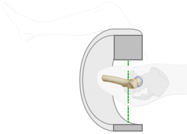
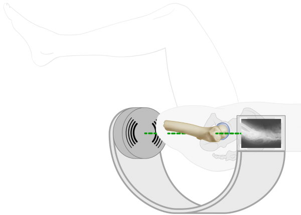
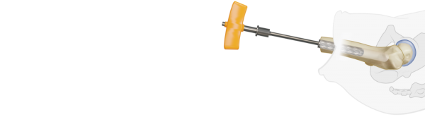
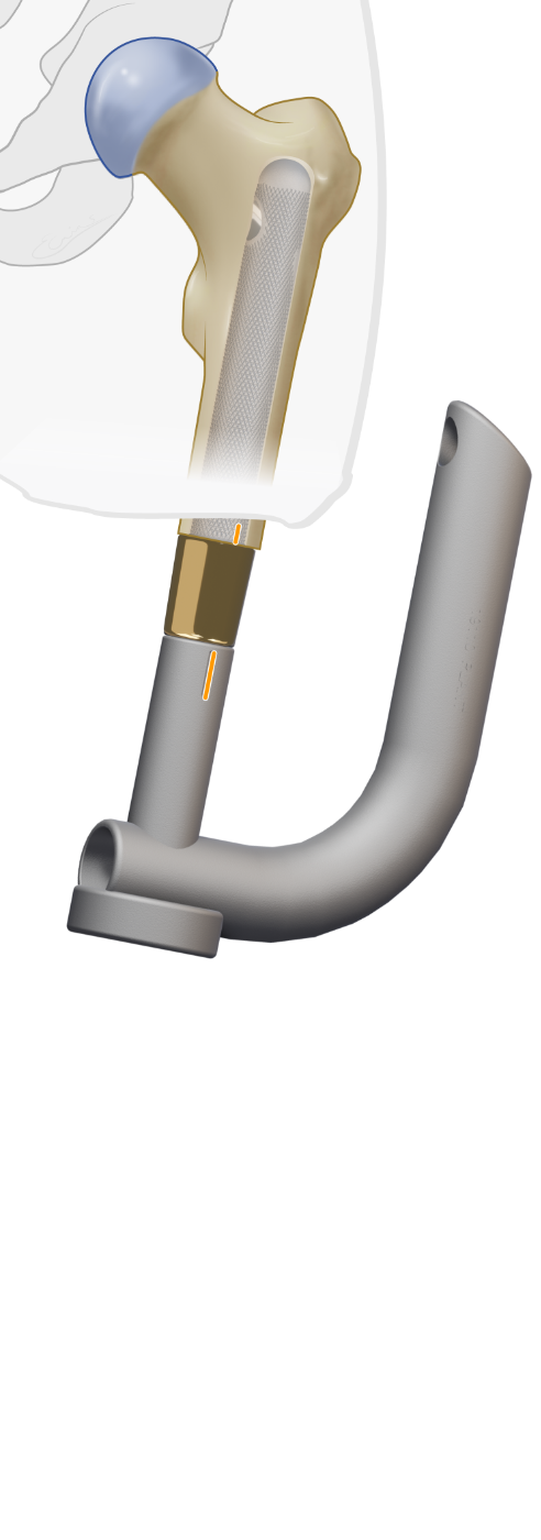
Fig Y12: Define correct implant rotation angle with Dummy Implant on Guiding Device
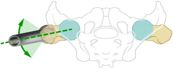
The Dummy Implant, installed on the Guiding Device, is inserted into the femur to determine the final rotation angle of the OFI-Y stem relative to the hip neck. With sagital Xray imaging of the hipneck the proper rotation angle of the Dummy Implant is defined in a way that the axis of the lagscrew hole exactly matches with the central longitudinal axis of the hip neck.
Fig Y15: Marking of correct rotation angle on the femur tip
The correct rotation angle is marked on the femurtip using the coagulator blade or by using the Aiming Device clamped on the distal femur tip.
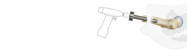
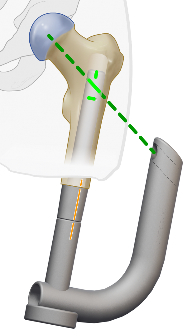
Fig Y16, Y17: Insertion of OFI-Y
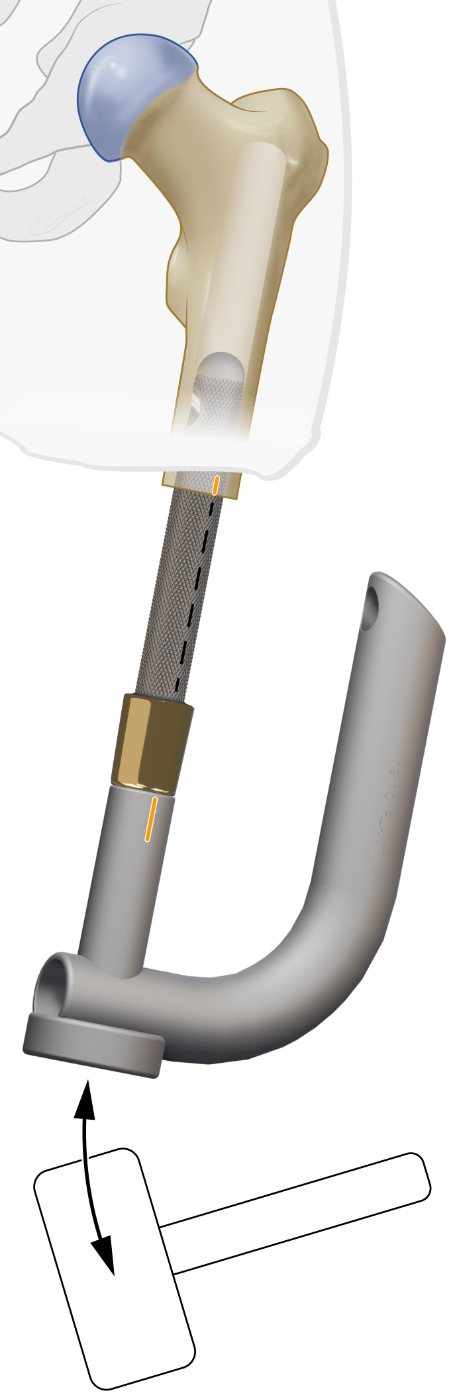
The OFI-Y stem is placed on the Guiding Device and press-fit hammered into the femur. During insertion check that the longitudinal mark on the OFI-Y stem exactly matches with the mark on the femurtip or Aiming Device.
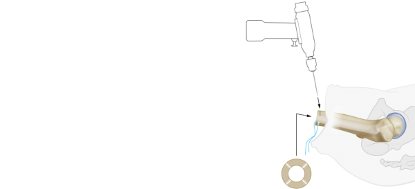
Fig Y18: Drill sleeve placement and K-wire insertion
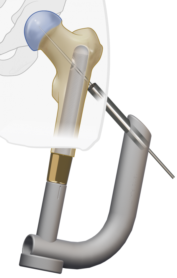
Place the Drill Sleeve in the Guiding Device and drill the Guide Wire under X ray guidance centrally in the hipneck
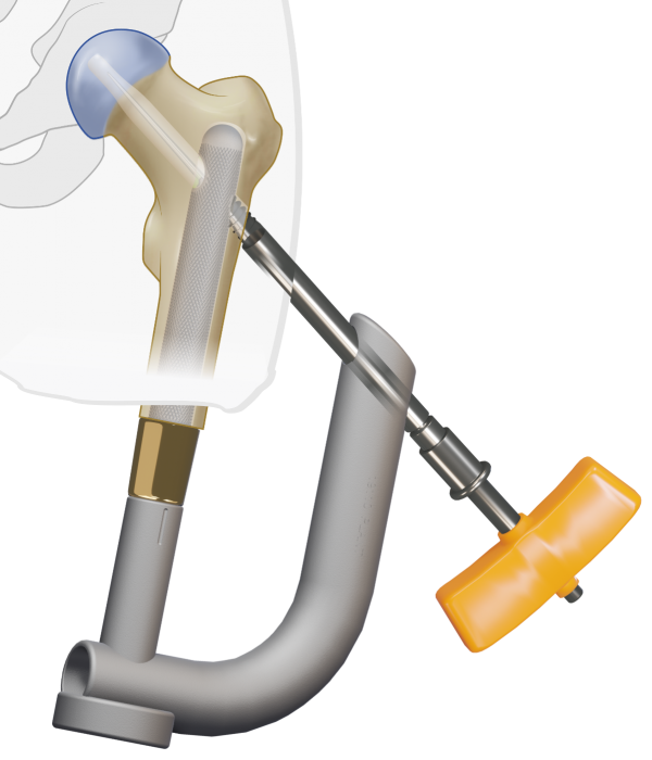
Fig Y19: Drill lag screw hole

Drill a hole with the Canulated Drill in the hip neck under constant alternately AP and sagital Xray imaging. Drill up to 10mm below the hip joint space.
Fig Y20, Y21: Lagscrew placement
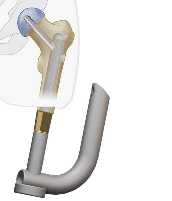
Define the Lag Screw length with the Ruler and screw the appropriate Lag Screw into the hip neck.
Y23: Completion of myodesis
After thoroughly rinsing the wound, the myodesis is performed by suturing the fascia layers of the thigh musculature to the distal tip of the femur with the trans-osseal Vicryl CP-1/CT-1 absorbable sutures. Once this is completed, the location of the future stoma is determined and subcutaneous fat overlying the head of the OFI-Y stem removed.
Y22, Y24: Skin closure
Wound closure is performed per standard technique with application of a stump pressure bandage. The surgical procedure is finished with intraoperative radiographic confirmation of the position of the OFI-Y stem.
BADAL X OFI-Y STEP 2
Surgery is performed under general or spinal anesthesia including prophylactic intravenous antibiotics e.g. vancomycin (1 g) or cephazolin (2 g) at induction of anesthesia. Surgery is performed in supine positioning of the subject and draping and prepping following local standard orthopedic protocols.
Fig Y25: K-wire insertion
A guide-wire is used to identify the center of the BADAL X implant.
Fig Y26: Skin incision
The Coring Device is passed over the guide-wire to cut the skin and create the stoma.
Fig Y27, Y28: DCA placement
The appropriate DCA is selected based on the thickness of the soft tissue layer in the stoma area. It is recommended that 2 to 3 cm of the gold coating of the DCA protrudes through the skin. The taper side with the two protruding pins of the DCA is inserted in the BADAL X implant and secured with the M6 Locking Screw using the Retainer and Hexa 4 Screwdriver. Use the Hammer and Punch to carefully further press the DCA male taper into the female taper receiver of the implant. Again use Retainer and Screwdriver to re-tighten the M6 Locking Screw. The stoma is covered with gauzes. Therby unfold a 10x10 cm gauze, wrap it around the DCA and tie it tightly around the DCA. This procedure may avoid minor bleedings from the stoma.
Fig Y29, Y30: Connector placement and prosthetic alignment
One week after stage two surgery or 3 weeks in case of single stage surgery the male part of the Luci Connector is placed on top of the distal DCA taper and secured with the M14 Abutment Screw. Preferably a certified prosthetist is required to attach the prosthesis, adjust the length and align the prosthesis in the frontal and sagital planes. Components (knee/foot) from the existing socket prosthesis are used to attach to the BADAL X. No specific prosthetic components are required to be used in combination with BADAL X. Based on the amount of hipflexion contracture and the length of the remnant in transfemoral amputation levels, the appropriate Offset Plate is selected. The Offset Plate is supplied with the BADAL X Connectors and used to compensated for the hip flexion contractures. During the first years after BADAL surgery the flexion contracture of the hip often decreases which may allow a smaller offset. The rule of thumb is that a smaller offset is better, because walking with a smaller offset is more efficient (less energy consumption). In femoral BADAL X, apply 7 degrees valgus between the connector and the prosthesis to restore the physiological leg axis alignment.
Rehabilitation starts immediately after fitting of the prosthesis (see rehabilitation protocols)
BADAL X OTI SURGERY
Fig T1: Surgery stage one for tibia
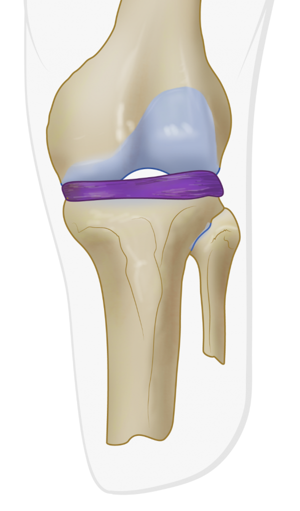
Calibrated AP X-rays and/or CAT scans and planning software (Traumacad) are used to: define the BADAL X implant size and to calculate the exact level of the bone cut. DCA size 70 and 80 are mostly used for transtibial amputees.
BADAL X is implanted in a one-, or two-stage surgical procedure. In cases where there is few soft tissue coverage of the residual bone, BADAL X may be installed in a single surgical procedure.
Surgery is performed under general or spinal anesthesia including prophylactic intravenous antibiotics e.g. vancomycin (1 g) or cephazolin (2 g) at induction of anesthesia. Surgery is performed in supine positioning of the subject and draping and prepping following local standard orthopedic protocols.
Fig T2: Skin incision
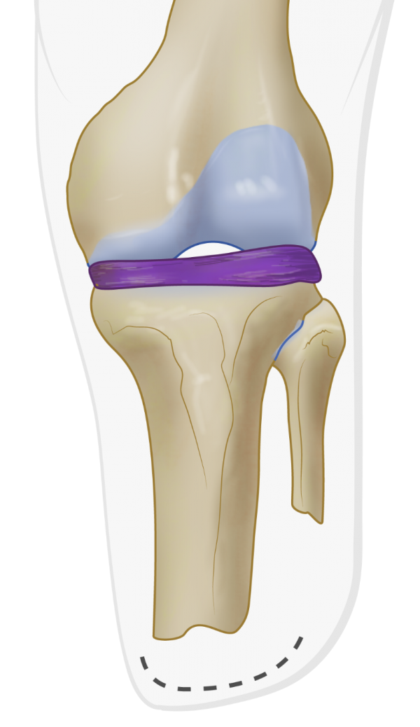
A mediolateral skin incision is performed across the tibia tip. If necessary, redundant skin and soft tissue is excised with a moon-/smiley like incision.
Fig T3: Cutting tibia tip with oscillating saw
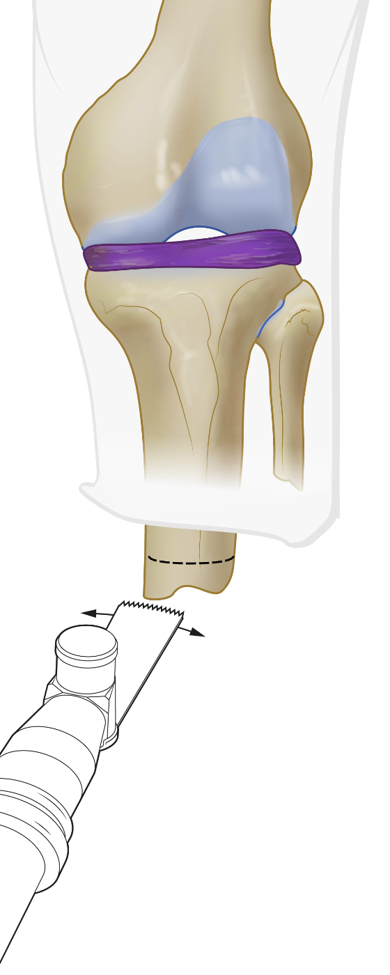
After releasing any tethering tissue, nerves are identified and, if present, any existing neuroma excised. The distal end of the tibia is cut with an oscillating saw according to calculations in the pre-surgical plan.
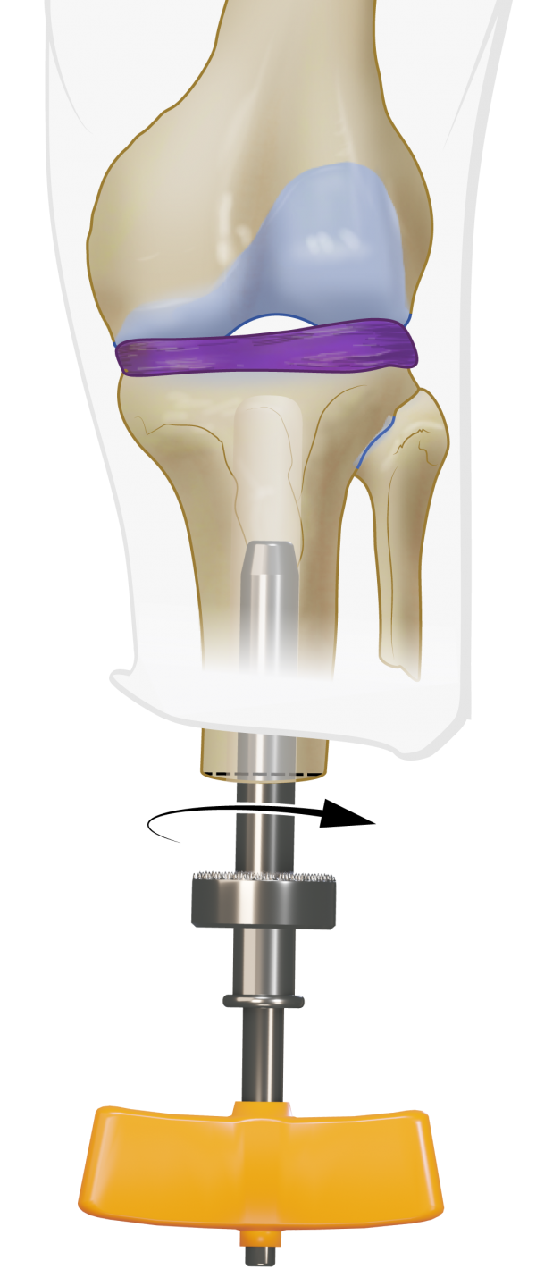
Fig T4: Tibia reaming with Rigid Reamers
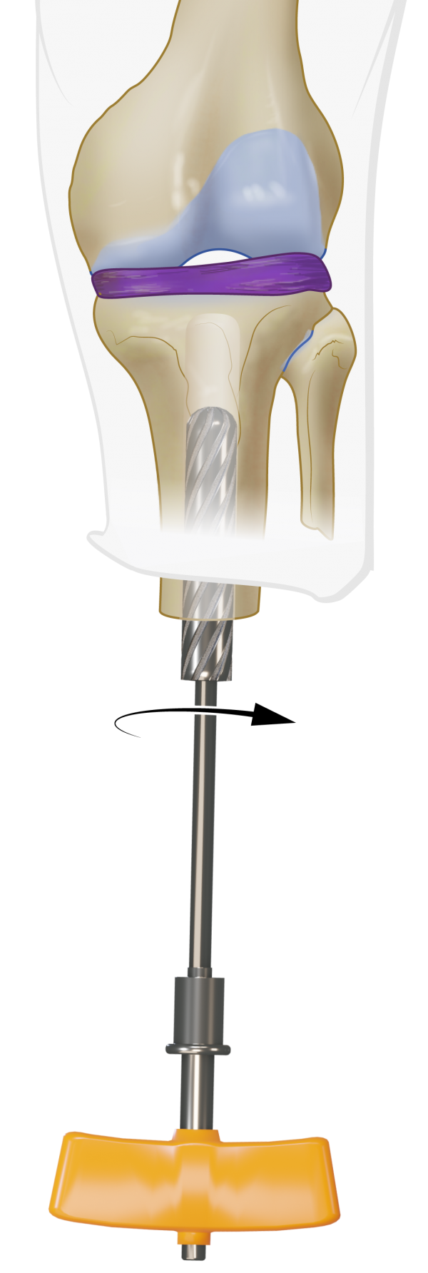
Use the Rigid Reamers on the T- handle to carefully ream the intramedulary canal of the tibia under constant alternating AP and sagital Xray image guidance and aim the Rigid Drill at the intercondylar eminentia. Reaming is terminated at the rigis reamer diameter equal to the diameter of OTI stem selected in the pre-surgical plan. Note that the diameter of the selected OTI stem is equivalent with the diameter of the last used Rigid Reamer to obtain optimal press-fit fixation
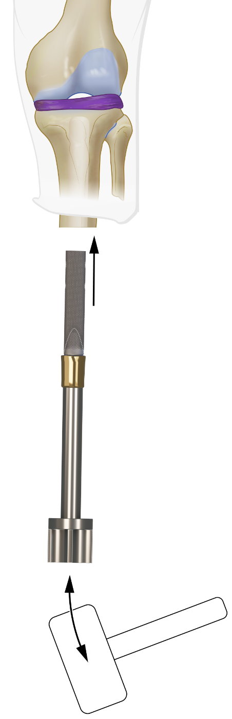
Fig T5: Tibia tip preparation with Distal Tip Rasp
Use the Distal Tip Rasp to create a plane exactly perpendicular to the longitudinal axis of the tibia. A myodesis is not required for tibia BADAL X implantation.
Fig T6: Create the drop-shape
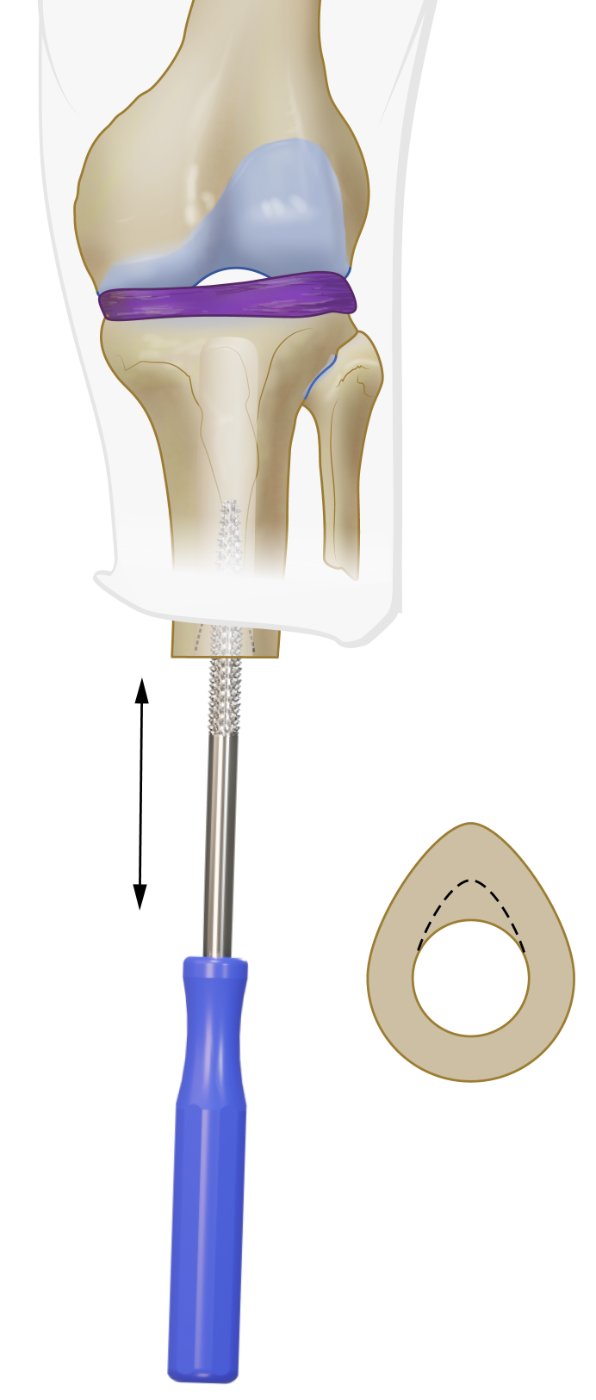
Prepare the distal intramedullary drop shape by reaming the ventral tibia tip with the Tibia Rasp.
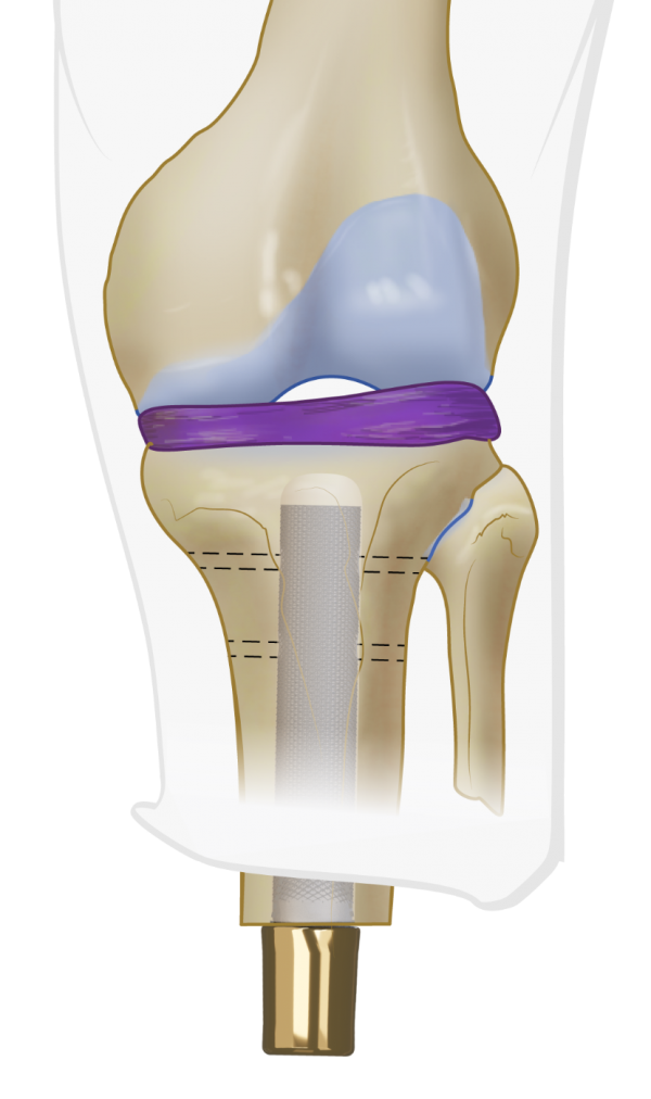
Fig T7, T8: Insertion of OTI
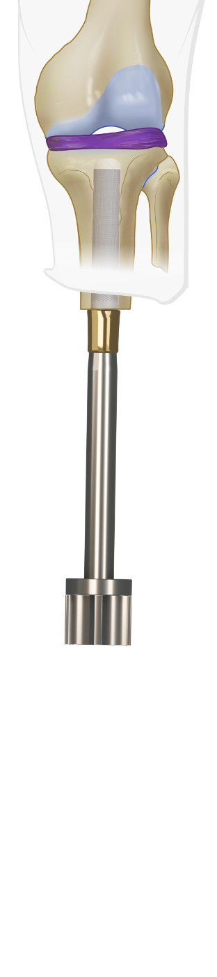
The OTI stem is placed on the Installer and press fit hammered into the tibia. Under Xray guidance.
Fig T9, T10: Prepare transverse screws
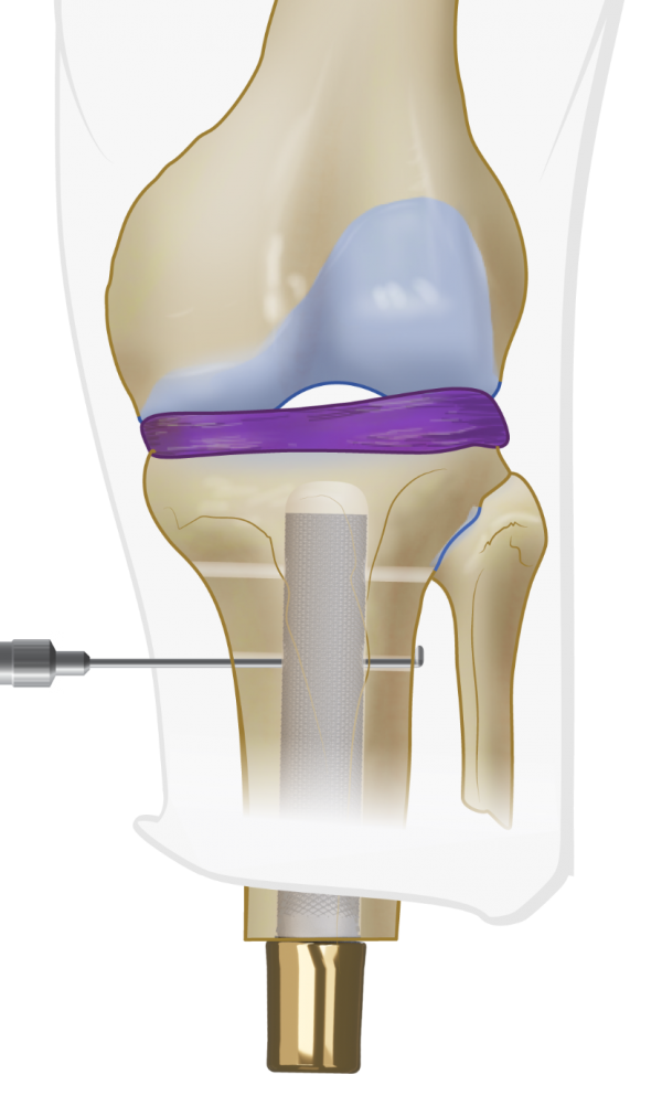
Drill one or two holes in the tibia to allow insertion of the Transverse Screws. Use the ruler to define the appropriate length of the Transverse Screws. Insert one or two Transverse Screws in tibia with the Hexa 4 Screwdriver.
Fig T12: Skin closure
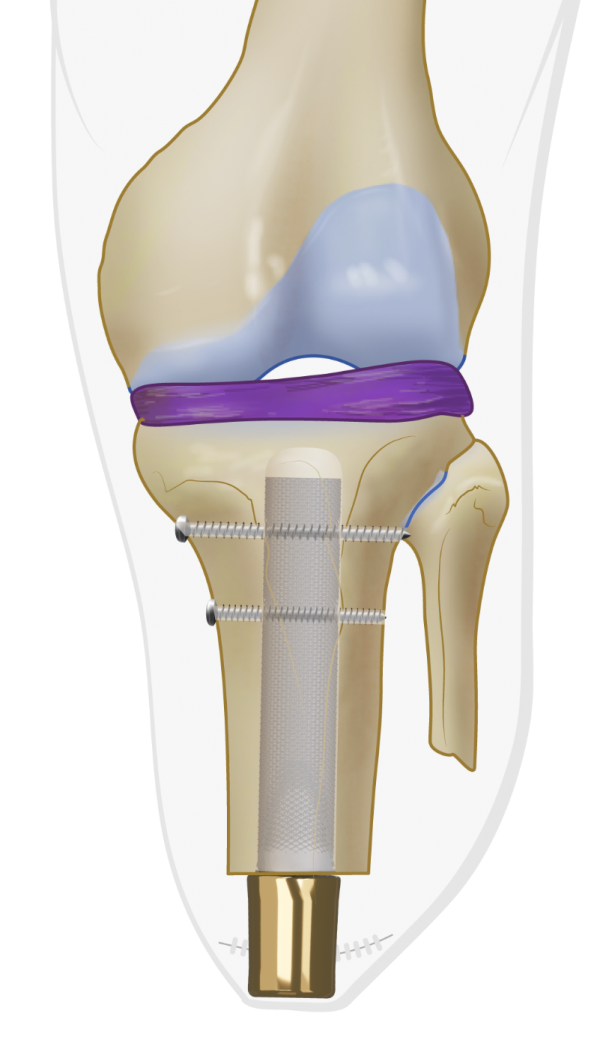
After thoroughly rinsing the wound, the location of the future stoma is determined and the wound closed per standard technique with application of a stump pressure bandage. The surgical procedure is finished with intraoperative radiographic confirmation of the position of the OTI stem.
BADAL X OTI STEP 2
Surgery is performed under general or spinal anesthesia including prophylactic intravenous antibiotics e.g. vancomycin (1 g) or cephazolin (2 g) at induction of anesthesia. Surgery is performed in supine positioning of the subject and draping and prepping following local standard orthopedic protocols.
Fig T13: K-wire insertion
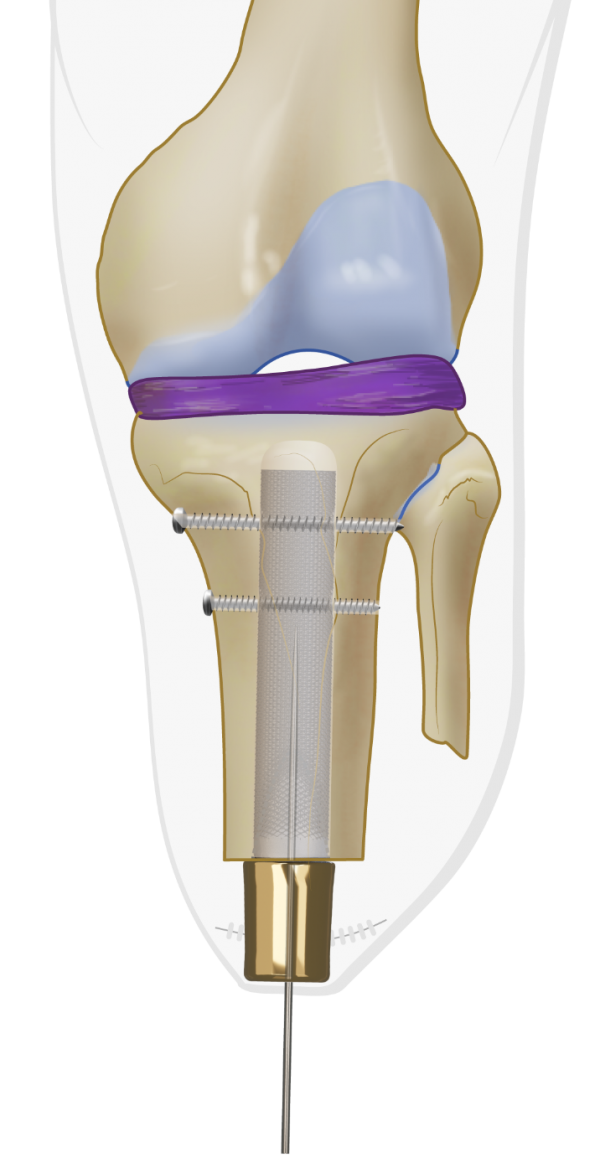
A guide-wire is used to identify the center of the BADAL X implant.
Fig T14: Skin incision
The Coring Device is passed over the guide-wire to cut the skin and create the stoma.
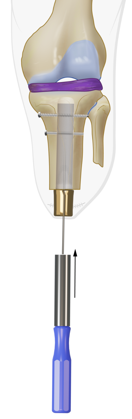
Fig T15, T16: DCA placement
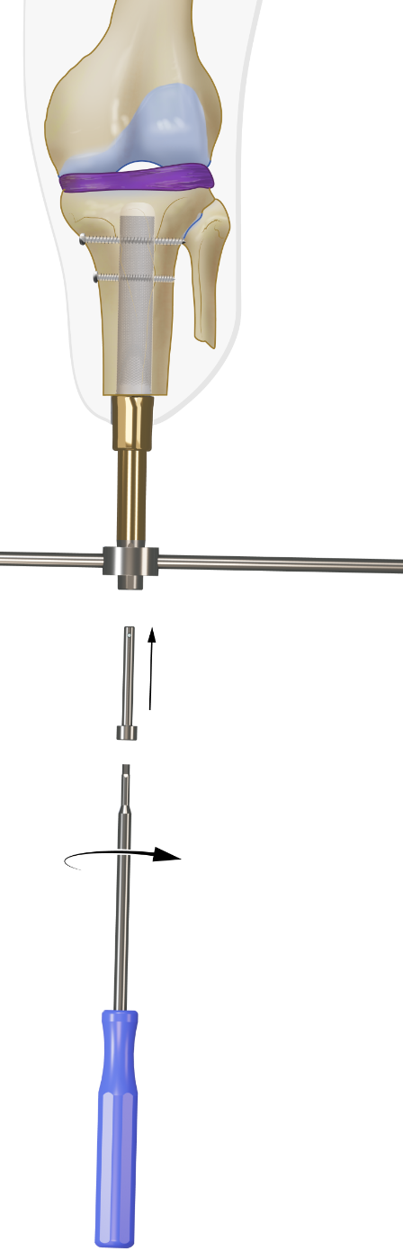
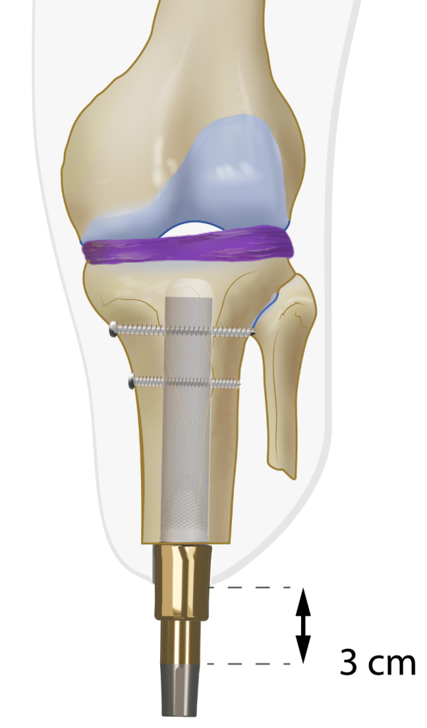
The appropriate DCA is selected based on the thickness of the soft tissue layer in the stoma area. It is recommended that 2 to 3 cm of the gold coating of the DCA protrudes through the skin. The taper side with the two protruding pins of the DCA is inserted in the BADAL X implant and secured with the M6 Locking Screw using the Retainer and Hexa 4 Screwdriver. Use the Hammer and Punch to carefully further press the DCA male taper into the female taper receiver of the implant. Again use Retainer and Screwdriver to re-tighten the M6 Locking Screw. The stoma is covered with gauzes. Therby unfold a 10x10 cm gauze, wrap it around the DCA and tie it tightly around the DCA. This procedure may avoid minor bleedings from the stoma.
Fig T17: Connector placement
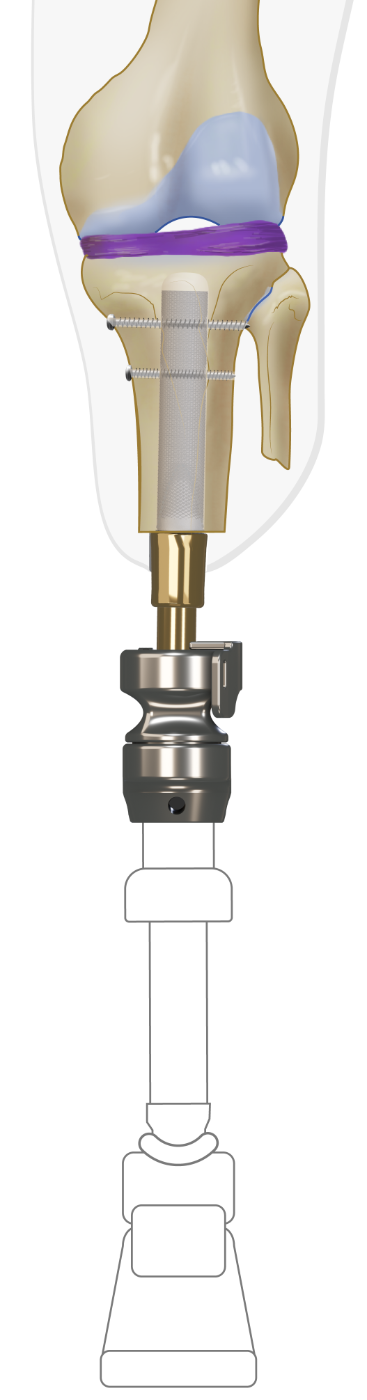
One week after stage two surgery or 3 weeks in case of single stage surgery the male part of the Luci Connector is placed on top of the distal DCA taper and secured with the M14 Abutment Screw.
Fig T18: Prosthetic adjust and alignments
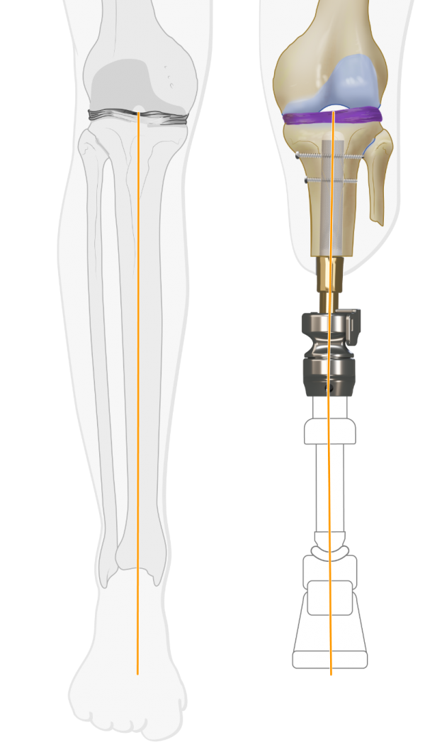
Preferably a certified prosthetist is required to attach the prosthesis, adjust the length and align the prosthesis in the frontal and sagital planes. Components (knee/foot) from the existing socket prosthesis are used to attach to the BADAL X. No specific prosthetic components are required to be used in combination with BADAL X. It is important to pay attention to the varus/valgus alignment in the frontal plane to avoid knee pain that may arise as a result of uneven knee load
Rehabilitation starts immediately after fitting of the prosthesis (see rehabilitation protocols)